Lubricant Analysis

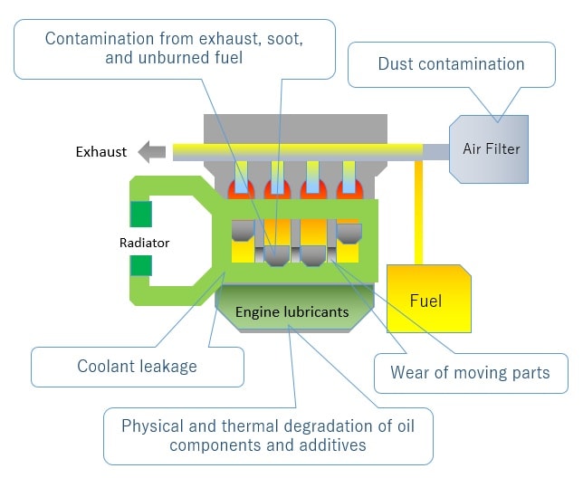
Engine lubricants play an important role in lubrication, cooling, cleaning, and rust prevention for vehicles, construction machinery, ships, airplanes, and other equipment with internal combustion or turbine engines.
Lubricants deteriorate due to decomposition and chemical changes of oil components and additives caused by physical and thermal stresses, as well as contamination by metal wear particles and incorporated fuel. As the lubricant deteriorates through use, its performance will decline and the inside of the engine can wear, leading to a decrease in service life and potential malfunction. Therefore, it is recommended to analyze the lubricant throughout its lifespan to assess its quality, utility, and remaining service life. These analyses can be accomplished with a number of instruments.
Analytical Techniques
1. lubricant deterioration analysis and additive analysis
2. Analytical Application to Lubricating Oil
1. lubricant deterioration analysis and additive analysis
| Analysis items (Elements) | Needed system | Standards | |
|---|---|---|---|
| Deterioration | Oxidation | FT-IR | ASTM E2412 |
| Nitration | |||
| Sulfate by-products | |||
| Contamination | Water | FT-IR | ASTM E2412 |
| Soot | |||
| Gasoline | GC | ||
| FT-IR | ASTM E2412 | ||
| Diesel | GC | ||
| FT-IR | ASTM E2412 | ||
| Coolant (B, Na, K) | GC | ASTM D4291 | |
| ICP-AES | ASTM D5185 | ||
| FT-IR | ASTM E2412 | ||
| Antifreeze (Na) | ICP-AES | ASTM D5185 | |
| Dust (Si) | |||
| Seal materials (Si) | |||
| Wear | Metals (Al, Fe, Cu, Cr, Ni, Zn, etc.) | ICP-AES | ASTM D5185 |
| Additives | Anti-oxidant (Zn, Cu, B) | ICP-AES | ASTM D4951 |
| FT-IR | ASTM E2412 | ||
| Anti-wear agents (B, Cu, K, S, Zn, etc.) | ICP-AES | ASTM D4951 | |
| FT-IR | ASTM E2412 | ||
| Detergent inhibitors (Ba, Mg, Ca, etc.) | ICP-AES | ASTM D4951 | |
| Corrosion inhibitors (Ba, Zn) | |||
| Anti-rusting agents (K, Ba) | |||
| Friction modifier additives (Mo) | |||
Lubricant deterioration analysis using compact FT-IR
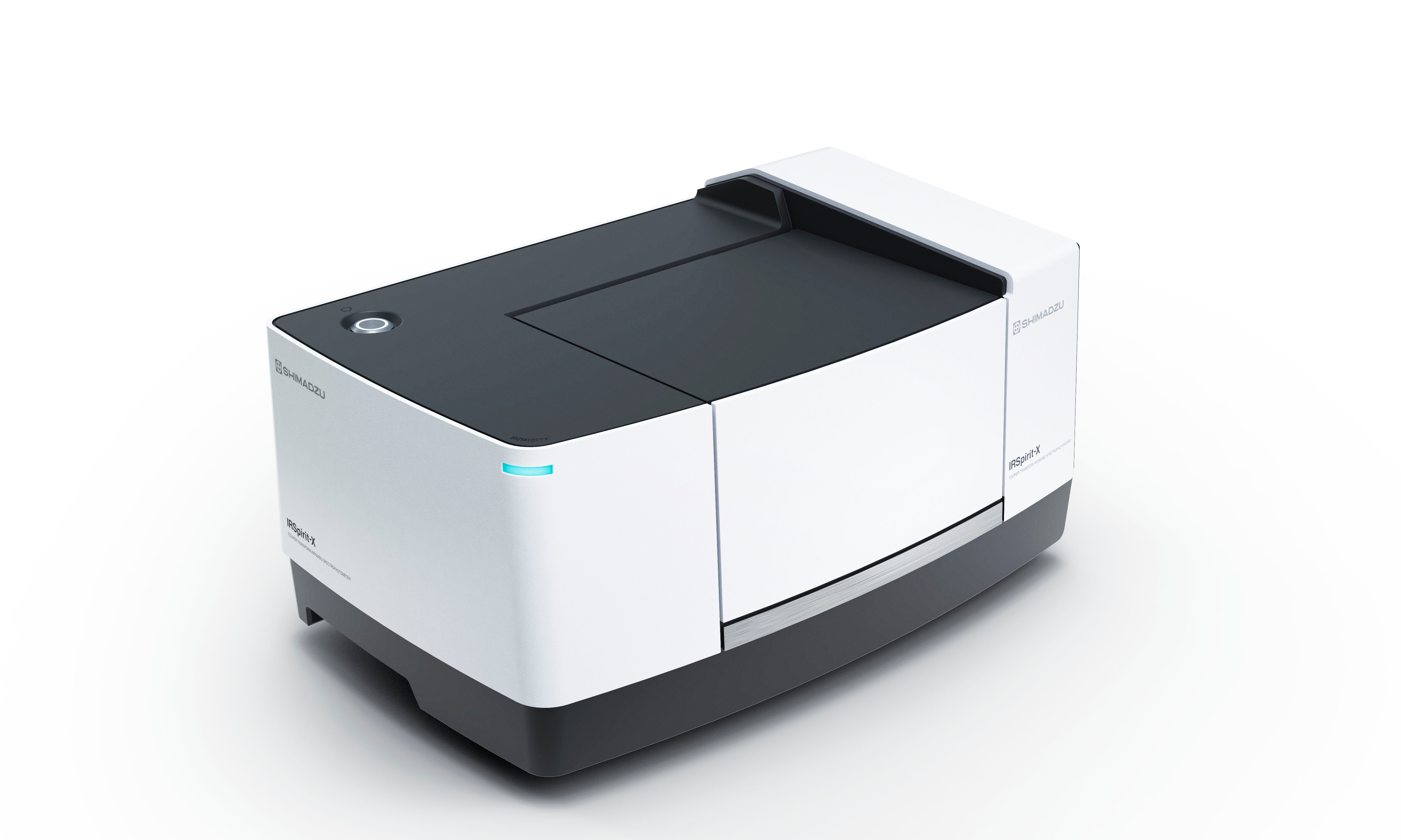
FTIR Spectrophotometer
Applicable Method
Condition Monitoring of Lubricant oil (ASTM E2412/D7418/D7414/D7415/D7412)
Rapid analysis of fuel dilution of engine lubricants by GC

Gas Chromatography
Applicable Method
Fuel dilution analysis of engine lubricants (ASTM D3524/D3525/D7593)
- Testing the Dilution Rate of Diesel in Engine Oil in Accordance with ASTM D7593
- Testing the Dilution Rate of Gasoline in Engine Oil in Accordance with ASTM D7593
- Testing the Dilution Rate of Diesel in Engine Oil in Accordance with ASTM D3524
- Testing the Dilution Rate of Gasoline in Engine Oil in Accordance with ASTM D3525
Analysis of Additive Elements, Wear Metals, and Contaminants in Used Lubricants using ICP-AES
ICP Emission Spectrometer
Applicable Method
Elements analysis in Lubricating oil (ASTM D4951/D5185)
2. Analytical Application to Lubricating Oil
Visualization of Lubricant Structure by SPM
In engine oil and other lubricants, additives are added to the base oil to improve performance. The additives form a thin adsorption film (tribofilm) on the metal surfaces of the sliding parts, reducing friction and wear. However, it is difficult to analyze the film in the lubricant. As a result, lubricant development sites repeatedly perform actual vehicle tests, engine tests, and other tests, to narrow down the search for additives and their optimal concentrations. This causes issues with time and expense.
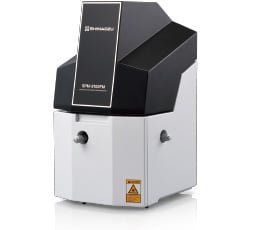
Using a mere 500 µL of lubricant, the SPM-8100FM high-resolution scanning probe microscope can analyze metallic surfaces in contact with a lubricant, at molecular level resolution. This holds promise as a new method, which will enable accelerated lubricant development by replacing a screening at the initial development stages with laboratory-scale materials testing.
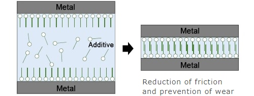
Diagram Showing the Behavior of the Additive

Anticipated Benefits of SPM
Example Analyses
-Structural Analysis of a Phosphate Ester Adsorption Film Formed in a Lubricant-
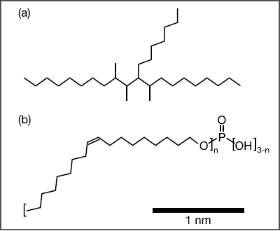
Molecular Structure (a) PAO, (b) Phosphate Ester
When a scanning probe microscope is used, structure at the molecular level can be evaluated by acquiring a topographic image (XY) of the adsorption film originating from the additive in the lubricant, and a Z-X cross-sectional Δf mapping image.
In this example, the SPM-8100FM next-generation scanning probe microscope, which features frequency modulation, is used to analyze the adsorption structure of a phosphate ester in a base oil of polyalphaolefin (PAO) on an iron oxide substrate. It is observed that the adsorption layer is different depending on the presence or absence of the phosphate ester.
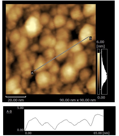
The surface is not covered by the phosphate ester adsorption film, so the contours of the particles are clearly visible.
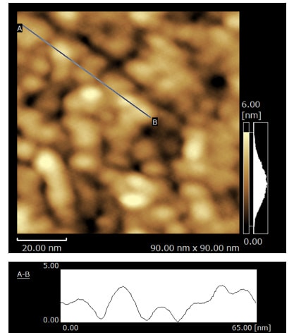
The surface is thinly covered by the phosphate ester adsorption film, so the contours of the particles are unclear.
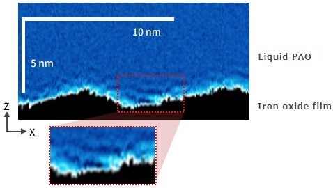
A layered structure is visible.

The disappearance of the layered structure suggests that the PAO molecules do not make direct contact with the iron oxide film surface. In other words, the iron oxide film surface is covered by the phosphate ester adsorption film.
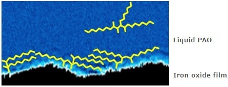
A multilayer structure is formed when the PAO molecules, which are in contact with the iron oxide film surface, lie horizontally and adopt a parallel orientation.

The PAO molecules do not make direct contact with the iron oxide film surface, so no layered structure is formed.
〔Source: Tribology No. 64, Vol. 11 (2019), Shiho MORIGUCHI, Ryohei KOKAWA, Teppei TSUJIMOTO, Akira SASAHARA and Hiroshi ONISHI: Analysis of Solid-Liquid Interface by Frequency Modulation Atomic Force Microscopy〕


