Stress-Strain Diagrams
Outline of Stress-Strain Diagrams
A graph showing the relationship between stress and strain obtained from strength tests is referred to as a stress-strain diagram. The horizontal axis of this diagram shows strain, the ratio of material deformation, and the vertical axis shows stress, the test force per unit area of material.
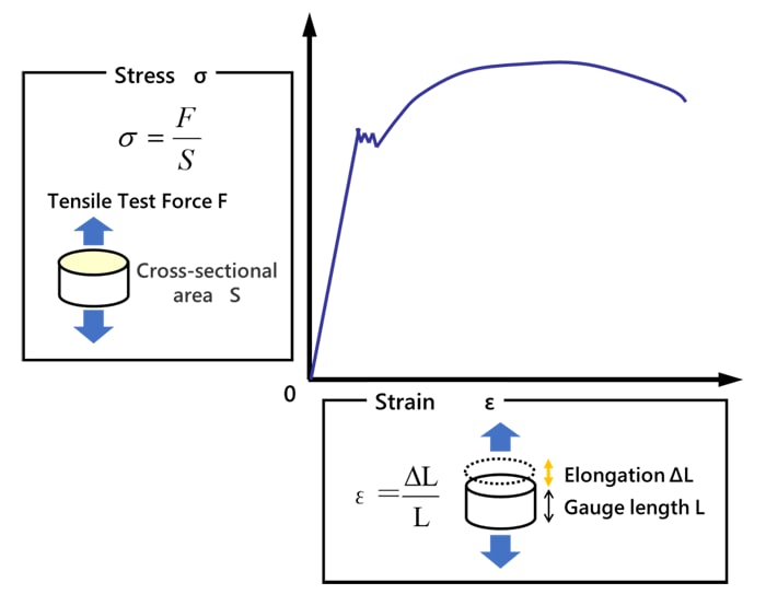
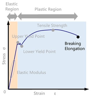
The diagram below shows a schematic diagram obtained from a tensile test of a steel material. As the test piece is stretched, the relationship between stress and strain is as follows.
- Linearly increasing at first
- Yield at a certain point
- Non-linear curve.

Characteristics Indicated from Stress-Strain Diagrams
The individual property values obtained from these stress-strain diagrams are described below.
Elastic Region / Plastic Region
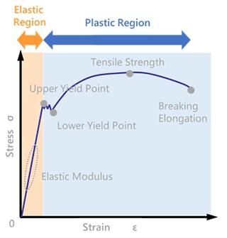
The right diagram describes the elastic and plastic regions. The orange area shows the elastic region, which "returns to its original shape like a spring when the force is removed. The blue area shows the plastic area, which is "the region that does not return to its original shape even if the force is removed. The elastic region provides data used in product design, which assumes that the shape will not deform, while the plastic region provides data for processing and durability.
Elastic Modulus
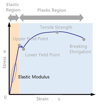
The elastic modulus is the modulus of longitudinal elasticity, also referred to as Young's modulus. It can be calculated from the slope of the linear range within the elastic region of a stress-strain diagram.
A higher elastic modulus means that the material is less likely to deform when a load of the same magnitude is applied and is therefore more rigid.
Tensile Strength
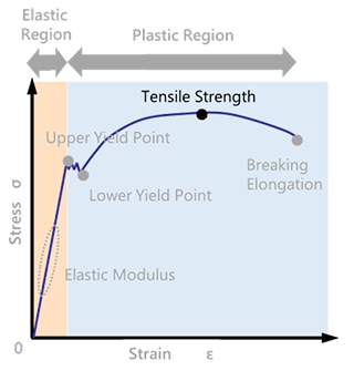
Tensile strength is the stress corresponding to the maximum test force in a tensile test, meaning the maximum force the material can sustain until it breaks.
Breaking Elongation
The point at which a test piece breaks in two in a tensile test is referred to as the breaking point, and the elongation at that point is referred to as the breaking elongation.
Upper Yield Point / Lower Yield Point
When an object is stretched, at a certain point the previously linear stress-strain diagram shows a different behavior. This occurs at the transition from the elastic deformation region to the plastic deformation region and is referred to as the yield point. When plastic deformation begins, there is a region where the stress decreases with respect to the displacement of the object.
The point at which this phenomenon begins is called the upper yield point and the minimum stress value after the upper yield point is called the lower yield point. This yielding phenomenon only occurs in steel materials and does not occur in non-ferrous metals such as aluminum and plastics.


