Introduction to mass analyzers

Figure 12. Schematic of Shimadzu's ion optical system (e.g. ion guide).
Mass spectrometry involves the control of ion movement by applying electrostatic fields. Ion optics is the term given to this electrostatic manipulation of ion flow in analogy with light manipulation by optical lenses. Figure 12 presents Shimadzu's ion optics system. It is used to focus the ions generated at the ion source into a beam. Simultaneously, it removes non-ionic gas particles from the system by progressive pumping and partitioning. This is important for achieving high-sensitivity analysis as residual particles interfere with the ion beam. Ion transmission and focusing is achieved by applying the required electric fields or radiofrequency voltage at the quadrupole ion guide.
How does the mass analyzer work? Normally when we measure mass (m), we use a mass scale or balance, which relies on the Earth's gravity. So, how do we measure the mass of a molecule, which is so extremely small that its gravitational force is almost too small to measure? The first occurrence started in 1912, where the English physicist, J. J. Thomson, utilized the fact that the flow of charged particles bends in an electric or magnetic field to develop an instrument that could separate charged particles by its mass number. In his instrument, which used a cathode ray tube, cations with identical ratios of charge (z) and mass (m) converged along the same parabola. When he measured the neon (Ne) gas molecule, the parabolas for 20Ne and 22Ne (both are monovalent cations) were slightly different, which proved the existence of isotopes. Therefore, with the use of this electromagnetic interaction, ions can be separated and measured according to m/z.
There are a variety of mass analyzers and they can be classified by how the ions are being introduced such as continuous or pulsed modes. Continuous MS allows an uninterrupted supply of ions to enter the mass analyzer while pulsed MS requires the ions to be introduced only at a specific time point. In a pulsed MS, ions from a continuous flow are usually accumulated and introduced together in pulses.
Apart from a single MS, there are tandem/hybrid arrangements, also known as MS/MS systems. Single mass analyzers such as the magnetic sector, quadrupole, and time-of-flight (TOF) were commonly used for measuring organic compounds, but the quadrupole model has gradually been increasing their share due to its relatively lower cost. Besides these mass analyzers, an ion trap MS system that temporarily accumulates ions of a selected range before separating them by mass, and a tandem/hybrid MS system that combines multiple MS units have been developed as well. These types of MS systems each take advantage of their respective features and are used according to various analytical objectives. This chapter elaborates on the separating and operating principles of the single mass analyzers and compares the characteristics, pros and cons for each of these mass analyzers.
Magnetic sector MS
Magnetic sector, a continuous MS, has been used historically the longest. As the name implies, the mass analyzer uses magnetic field to separate ions of different m/z values (Figure 13). High voltage is first applied to the ions to accelerate them into the magnetic sector. A continuous ion source is generated and supplied from the ionization unit to the magnetic sector. Once the ions enter, are exposed to the magnetic field. As a result, ions are deflected according to Fleming's left-hand rule*4. The deflections differ based on their m/z where lighter ions (of the same charge) will experience more deflection.
*4 Fleming's left-hand rule can predict the direction/force of the movement when there is an electric current moving in an applied magnetic field. As a result, ions are accelerated in a direction perpendicular to the current and magnetic field, resulting in a curved deflection path for the ions in the magnetic sector MS.
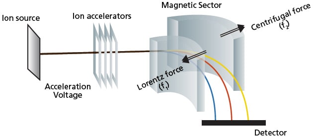
Figure 13. Schematic of magnetic sector MS.
Equation 3:
f1 = Bzev
Equation 4:
![]()
Equation 5:
![]()
Equation 6:
![]()
Equation 7:
![]()
B: magnetic flux density
z: charge of the ion
e: elementary charge
v: velocity of the ion
m: mass of the ion
r: path radius
V: acceleration voltage applied to ions
Ions experience a Lorentz force (f1) from the magnetic field that can be calculated according to Equation 3. As the direction of the ion changes, a centrifugal force (f2), expressed by Equation 4, acts on the ion. For the ions to pass through the magnetic field region and reach the detector, it must travel along a curved path of a given radius (r) where f1 and f2 are balanced (Equation 5). Furthermore, the kinetic energy of ions accelerated by voltage V is shown in Equation 6. By eliminating the velocity of the ion (v), Equations 5 and 6 are simplified to give Equation 7. By keeping the ion acceleration voltage V constant and varying the magnetic flux B (or keeping B constant and varying V), a detector placed on the corresponding path radius r could detect any mass m (given the same charge).
In reality, only one ion detector is used and both the acceleration voltage (V) and curve path radius (r) are kept constant while the magnetic flux density (B) is scanned. This means that ions with different masses (m) all pass along the same path through the magnetic field, one after another, and reach the detector. One mass spectrum is obtained from each scan of the magnetic field. That is to say that magnetic sector mass analyzer function by ion transmission and scanning mode. Besides the described single magnetic sector MS, there are also models of MS with both the electric sector and magnetic sector in a single MS, which is known as a dual-focusing MS. This setup is able to focus and converge ions of different energy and identical mass thereby obtaining higher mass resolution.
Some of the key features of magnetic sector MS are its high resolution and high dynamic range. The measurement range of magnetic sector MS systems typically is about 10 to 10,000, though it depends on the acceleration voltage V and instrument design. Resolution of about 2000 can be obtained using a single-focusing magnetic sector model or several tens of thousands using a dual-focusing magnetic sector model. Before the recent introduction of the high-performance time-of-flight (TOF) MS and ion-cyclotron-resonance (ICR) MS systems, the dual-focusing magnetic sector spectrometer was the only MS capable of such high-resolution measurements.
However, to improve the performance of the magnetic sector MS, the strength of the magnetic field needs to be raised which means costly and larger systems are required. This limits the development of the magnetic sector MS. In addition, magnetic sector MS systems require an extremely high vacuum level of 10-7 Pa, causing difficulty in the LCMS interface. Furthermore, they have the disadvantage of a slower scan speed than other MS systems. Therefore, these mass analyzers are now rarely used in LCMS systems. On the other hand, they interface relatively easily to a GC unit. Consequently, such GC-MS systems are used for dioxin analysis due to the outstanding highresolution selected ion monitoring (HR-SIM) capability of magnetic sector MS.
Quadrupole MS
The other MS which functions by scanning of ions and allowing ion transmission is the single quadrupole mass analyzer. As its name suggests, it contains four parallel cylindrical metal rods (electrodes with a hyperboloidal interior surface) inside a vacuum chamber, positioned equidistant from the center axis (Figure 14). Both a direct current (D.C.) and high frequency alternating current or radiofrequency (RF) are applied to the quadrupole, so that only the ions with the target m/z successfully pass through the quadrupole and get to the detector. The quantity of ions that reach the detector is converted to a signal and output to a computer.
Continuous ion source generated in the ionization unit are first accelerated in the z-direction (Figure 14, green arrow) by a relatively weak voltage of only a few dozen volts. These ions pass through a tiny orifice and enter the quadrupole. Voltage of the same polarity is applied to diagonallyopposite poles and opposite voltage polarity is applied to adjacent poles as depicted by the blue and red rods in Figure 14. When a combination of the direct current voltage and high-frequency alternating current voltage is applied to each pole, an electric field with a rapidly varying phase is generated within the quadrupole.
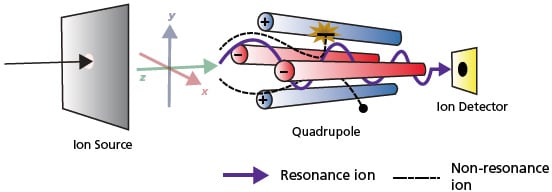
Figure 14. Schematic of how Quadrupole MS works.
Consequently, ions passing through this electric field oscillate in the x- and ydirections. When a given set of parameters are applied to the poles, certain ions of a specific m/z range maintain a stable oscillation and pass through the quadrupole to reach the detector (Figure 14, resonance ion). On the contrary, the oscillations of ions with other m/z values become unstable, causing them to collide with the poles, fly out of the system, and not be detected (Figure 14, non-resonance ion).
The oscillation of ions within the quadrupole MS is known to occur according to the Mathieu Equation (Equation 8). The motion of the ion in a quadrupole follows this equation regardless of its initial velocity or position. Figure 15 illustrates how the equation is solved which is also the Mathieu stability diagram for the stable regions for ions in a quadrupole MS system.
As illustrated in the shaded areas in Figure 15, the conditions required for stable ion oscillation are determined by the mass and oscillation frequency of the ion as observed in the Mathieu Equation.
Equation 8:
Mathieu Equation
![]()
m: mass of the ion
z: charge of the ion
K: constant
V: voltage applied
r: effective distance between the electrodes
ω: oscillation frequency
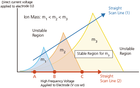
Figure 15. Mathieu stability diagram for the stable regions for ions in Quadrupole MS system.
The region of stability is different for ions with masses m1, m2 and m3. If the voltage is varied while keeping the ratio between the direct current voltage (y-axis) and high-requency alternating current voltage (x-axis) constant, a straight scan line 1 is obtained. This scan line passes through respective regions of stability for ions with masses m1, m2 and m3. Consequently, these ions are passed through the quadrupole consecutively in the same order (m1, m2 and m3). In this way, a mass spectrum is obtained for ions with masses ranging from small to large.
For a single quadrupole MS system, it can operate in two modes: (A) Scan and (B) Selected Ion Monitoring (SIM). In scan mode, the voltages to the quadrupoles is configured such that the entire mass range specified is scanned sequentially with appropriate dwell time*5 for each m/z value. As illustrated in Figure 16A, the blue ions, followed by red ions and lastly yellow ions passed through the quadrupole sequentially and gets detected. The result is a record of the ion abundancein the specified range of the mass spectrum. For the SIM mode (Figure 16B), only the selected m/z (red ion) is monitored, passed through the quadrupole and detected. This SIM mode offers higher sensitivity and avoids the effects of unwanted analytes and impurities.
*5 Dwell time is the time allocated for measuring or acquiring the data of an ion of a particular mass-to-charge ratio in a mass spectrometer. It is the acquisition portion of the LCMS duty cycle. The longer the dwell time, the greater the number of target ions detected. In simultaneous multicomponent analysis, dwell time may be shortened for each target component.
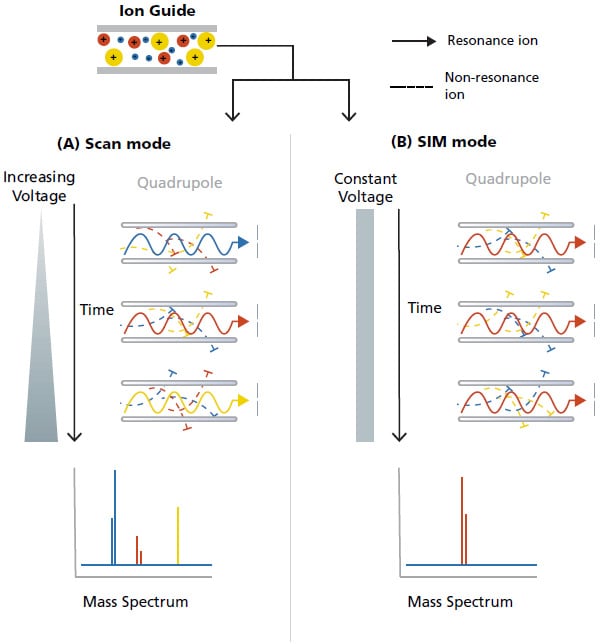
Figure 16. Schematic of the (A) scan mode and (B) SIM mode in Quadrupole MS.
Since the separating principle of the quadrupole MS systems is straightforward, they are comparatively easier to operate and maintain. Also, the quadrupole is compact in design, robust and relatively inexpensive. Consequently, they are widely adopted as a general-purpose analytical instrument. Furthermore, unlike other MS which require high vacuum levels, quadrupole MS can adequately function at lower vacuum levels (≒ 10-2 to 10-3 Pa). Even if they are interfaced with a GC or LC unit, the drop in vacuum level caused by the interface has minimal effect on the mass separation performance, making it the best suited for interfacing with chromatographic techniques.
Quadrupole MS demonstrates good scan speed and sensitivity. With a maximum scan speed of 15,000 amu/second, it is capable of measuring at higher scan speeds than the magnetic sector MS. Its mass range can reach up to 2,000 m/z which enables the qualitative analysis in a practical range of molecular masses. In addition, it allows highspeed polarity switching, which facilitates simultaneous monitoring of multiple selected ions of different polarity. With the use of the SIM mode in a quadrupole MS, it can deliver a high-sensitivity quantitative analysis of a large number of target compounds, making it a widely recognized system among MS.
Time-of-Flight (TOF) MS
Unlike magnetic sector and quadrupole MS, Time-of-Flight (TOF) MS is a pulsed and non-scanning MS. It has a simple construction, consisting of an accelerator, a field-free region, a reflectron and detector inside a high vacuum chamber called a flight tube (Figure 17).
TOF MS separates and detects ions of different m/z by measuring the time taken for the ions to travel through a field-free region. First, ions generated in an ionization unit are accumulated and introduced in pulses to a flight tube. These ions are accelerated by applying a high acceleration voltage between the electrodes. The corresponding kinetic energy is obtained as described in Equation 9. Given a constant acceleration voltage as well as kinetic energy, each ion flies at its unique velocity inside the flight tube to reach the ion detector, which is higher for ions with smaller masses and lower for ions with larger masses.
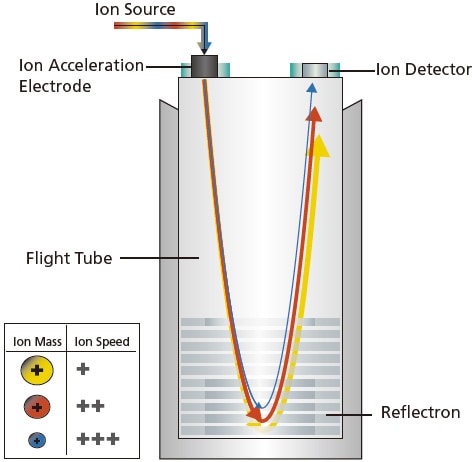
Figure 17. Schematic of a TOF MS.
Equation 9:
![]()
Equation 10:
![]()
T: Time of flight
m: mass of the ion
v: velocity of the ion
z: charge of the ion
e: elementary charge
V: acceleration voltage applied to ions
L: flight distance in TOF
As shown in Equation 10, Time of flight (T) is proportional to the square root of m/z, i.e. for a fixed flight distance (L), ions with smaller m/z reach the detector sooner than those with larger m/z. Therefore, by keeping all other parameters constant, the time of flight (T) can be converted directly to m/z, which is how a mass spectrum is generated in a TOF MS. Since there is no limit to the time of flight in TOF MS, it can theoretically measure an unlimited mass range.
Due to its operating principle, TOF MS systems do not introduce ions into the analyzer until after the previous group has reached the detector. Therefore, it has good compatibility with ionization methods that ionize molecules in pulses, such as laser ionization. This analytical technique has been extremely useful for proteomics using MALDI-TOF MS systems, where proteins are identified by comparing measurements of fragmented peptides with a database. With advancements that minimizes the differences in the kinetic energy of ions, such as the use of reflectron and pulsed extraction methods, TOF MS systems are currently being utilized for high-resolution MS.
Ion Trap (IT) MS
IT MS is based on an ion trapping mechanism and pulsed MS. There are several variations of IT MS, for example the 2D linear quadrupole IT MS and the 3D ring IT MS and the components and system configurations may vary slightly. These IT MS employ the same principle as the quadrupole MS and the motion of ions within the mass analyzer follows the Mathieu Equation (Figure 15). In this section, the 2D linear quadrupole IT MS are described in greater detail. It generally consists of a donut-shaped ring electrode sandwiched between two end-cap electrodes (Figure 18). An ionization unit is located at the entrance and a detector at the exit. Just like a quadrupole system, the internal surface of electrodes is hyperboloidal, which can be thought of as the entrance and exit of a quadrupole connected in a ring shape. Normally, the IT MS is used without applying the direct current voltage (U) to the electrodes, which corresponds to movement and operation along the horizontal axis.
To measure a spectrum, end-cap electrodes are first grounded, then a low high-frequency voltage is applied to the ring electrode. The ions are introduced into the IT MS in a pulse mode, where they are all temporarily trapped inside the electrode. This state, where the ions with varying mass are experiencing stable oscillations, is indicated in Figure 18A. Subsequently, to detect a specific ion, the high-frequency voltage is gradually increased (Figure 15, straight scan line 2), while keeping the direct current (U) to zero. As the voltage increases (Figure 15), the oscillation of the blue ion becomes unstable at point B in the Mathieu diagram and the red ion becomes unstable at point C, at which time these ions are discharged via the hole in the end-cap electrode (Figure 18B). Quadrupole MS systems separate and detect masses by letting oscillating ions pass through the quadrupole to reach a detector, whereas ion trap MS systems separate and detect masses by discharging ions with unstable oscillations from the system.
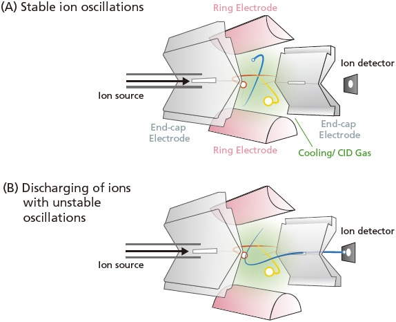
Figure 18. Diagram of an IT MS.
As the name implies, ion trap MS systems trap the generated ions before separating them by mass. Consequently, they cannot perform selected ion monitoring (SIM) transitions and measurements for transmission type MS. Furthermore, they operate by pulsed mode and only a limited quantity of ions can be trapped, resulting in a narrower dynamic range than quadrupole MS systems. However, all trapped ions are detected in the IT MS, this provides higher sensitivity in scanning analysis than quadrupole models. In addition, it enables the trapping of a specific ion, fragmenting it and then trapping a specific product ion for further fragmentation, and so forth. Therefore, IT MS is considered a mass spectrometer specialized for elucidating the fragmentation pathway for structural determination of a target molecule.
In addition to the two kinds of IT MS, there are other similar trapping type of MS such as the Fourier Transform Ion Cyclotron Resonance (FT-ICR) and Orbitrap. They adopt similar mechanism and principles. In the FT-ICR setup, the use of both the electric and magnetic field generates the stable oscillation and motion of the ions. To detect the ions, the selected ions are accelerated such that its radius of oscillating motion increases, the oscillation becomes unstable and eventually the ion gets removed. By determining the cyclotron frequency, it can be Fourier transformed and the ion mass is deduced. For Orbitrap MS systems, it only requires the use of electric field to trap and separate the ions. These MS systems demonstrate excellent mass resolution and mass accuracy.
Comparison of mass analyzers
It is important to note that no single mass analyzer is excellent for all analyses. Therefore, it is important to understand the different principles, features and characteristics of these mass analyzers and choose the one suitable for your needs. Some of the key advantages and limitations of these single mass analyzers are listed in Table 4.
| Mass Analyzer | Description | Advantages | Limitations |
|---|---|---|---|
| Magnetic Sector | Scanning Continuous |
|
|
| Quadrupole | Scanning Mass Filter Continuous |
|
|
| Time-of-Flight | Non-scanning Pulsed |
|
|
| Ion Trap | Trap Pulsed |
|
|
Mass spectrometers are now used for an extremely diverse range of applications, each with its own characteristics. Therefore, it is not easy to decide in a simple manner which type of MS is optimal. In terms of cost and ease-of-operation, quadrupole mass analyzers have been increasing in market share for LCMS applications. Likewise, ion trap and TOF MS systems offer performance not obtainable from quadrupole models, so their usage and popularity is also continuing to increase. This means the MS system must be selected based on objectives, be it sensitivity, peak resolution, or a compact general-purpose system. In summary, it is important to consider and choose a MS system that allows benefiting from the advantages offered by each ionization method and mass separation technique.


